Difference between revisions of "Tutorials:3D Meshing Part VII"
| (3 intermediate revisions by 3 users not shown) | |||
| Line 1: | Line 1: | ||
| − | ==3D Meshing | + | {| style="border:none; background-color:#f9f9f9" width="100%" align="center" |
| + | |- | ||
| + | !align="left" style="font-weight:normal" |[[Tutorials:3D Meshing Part VI|<<Back]] | ||
| + | |align="center"|[[Tutorials:3D Meshing Index|Index]] | ||
| + | |align="right"|Next>> | ||
| + | |} | ||
| + | |||
{{Infobox Tutorial | {{Infobox Tutorial | ||
| Line 11: | Line 17: | ||
}} | }} | ||
| + | |||
| + | ==3D Meshing, Part VII: Organic Modeling== | ||
In this topic we will talk about Organic 3D models. For organic items, we need smooth corners and gradual bends. The smooth corners is actually easy, you get those by default when you leave the entire object in the same smoothing group. Smoothing groups will be in a later lesson. | In this topic we will talk about Organic 3D models. For organic items, we need smooth corners and gradual bends. The smooth corners is actually easy, you get those by default when you leave the entire object in the same smoothing group. Smoothing groups will be in a later lesson. | ||
| Line 16: | Line 24: | ||
But to get smooth bends, you need multiple bone assignments and skin weights. In previous lessons we learned about creating joints and assigning parts of the mesh to them. But we assigned the parts entirely to one joint or another. | But to get smooth bends, you need multiple bone assignments and skin weights. In previous lessons we learned about creating joints and assigning parts of the mesh to them. But we assigned the parts entirely to one joint or another. | ||
| − | In this lesson, we will learn to assign the same parts to more than one bone at a time, with | + | In this lesson, we will learn to assign the same parts to more than one bone at a time, with different levels of influence. This will enable smooth bending. |
To start, we will make a simple base model from a single cylinder, and add two joints. Then we will explore the differences in assignment methods and their effects. | To start, we will make a simple base model from a single cylinder, and add two joints. Then we will explore the differences in assignment methods and their effects. | ||
| − | So fire up MilkShape, on the Model tab pick cylinder, set the Stacks to 6, Slices to 12 and use the "Don't Close" option. (Note: This isn't a critical step, but if you use other values your cylinder will look different than mine). Then go to the Face->Smooth All | + | So fire up MilkShape, on the Model tab pick cylinder, set the Stacks to 6, Slices to 12 and use the "Don't Close" option. (Note: This isn't a critical step, but if you use other values your cylinder will look different than mine). Then go to the Face->Smooth All menu item to get rid of the black and show a smooth texture. If your cylinder is not centered over the origin with one end on the ground, use Move to place it so. |
[[Image:organic_start.jpg|300x300px|right]]Your mesh should look like this one:<br style="clear:both" /> | [[Image:organic_start.jpg|300x300px|right]]Your mesh should look like this one:<br style="clear:both" /> | ||
| Line 27: | Line 35: | ||
Next, we will add two joints. One will be at the bottom and we will call it base. In the Model tab, select Joint and click at the origin. Then go to the joints panel and see that there is a joint1 and that it is highlighted. Type "base" in the box next to the Rename button and click on Rename. The name in the list should change to base and the item remain highlighted. | Next, we will add two joints. One will be at the bottom and we will call it base. In the Model tab, select Joint and click at the origin. Then go to the joints panel and see that there is a joint1 and that it is highlighted. Type "base" in the box next to the Rename button and click on Rename. The name in the list should change to base and the item remain highlighted. | ||
| − | Being highlighted means it is selected, and then the next step will create a joint that is a child of base. Go back to the Model panel, and first we will set the base joint to the origin by using Move and putting 0 0 0 in | + | Being highlighted means it is selected, and then the next step will create a joint that is a child of base. Go back to the Model panel, and first we will set the base joint to the origin by using Move and putting 0 0 0 in the position boxes, choosing absolute and then clicking on Move. Since only the new joint is selected, it moves to the origin and the cylinder stays still. |
Now click on Joint again and place a second joint in the middle of the cylinder, halfway up. If your click left it placed incorrectly, use the Move button and drag it to the correct spot. Being pretty close will make the animation we do later act the way we expect. | Now click on Joint again and place a second joint in the middle of the cylinder, halfway up. If your click left it placed incorrectly, use the Move button and drag it to the correct spot. Being pretty close will make the animation we do later act the way we expect. | ||
| Line 38: | Line 46: | ||
First, we are going to assign joints the way we learned before, do a simple test animation step and see what happens. | First, we are going to assign joints the way we learned before, do a simple test animation step and see what happens. | ||
| − | From the Edit menu, Select None. Go to the Joints panel and double-click on the base joint to select it. Then go back to the Model panel and choose the Select button. For the options, click on Vertex and make sure "ignore backfaces" is UNchecked. Now, in the front, back, left or side view, click and drag a box around the lowest three rows of vertices and verify that they all turned red, indicating they are selected. Then go to the joints panel and click on assign. | + | From the Edit menu, Select None. Go to the Joints panel and double-click on the base joint to select it. Then go back to the Model panel and choose the Select button. For the options, click on Vertex and make sure "ignore backfaces" is '''UNchecked'''. Now, in the front, back, left or side view, click and drag a box around the lowest three rows of vertices and verify that they all turned red, indicating they are selected. Then go to the joints panel and click on assign. |
Now, a clever shortcut. Instead of repeating the previous steps for selecting the rest of the vertices, double-click on the knee joint. Then click on the "SelUnAssigned" button. The remaining vertices, which are unassigned, will be highlighted. Then just click on assign to set them to knee. Use the "Draw vertices with bone colors" checkbox to make sure that the bottom is assigned to the base and the middle row up is assigned to knee. | Now, a clever shortcut. Instead of repeating the previous steps for selecting the rest of the vertices, double-click on the knee joint. Then click on the "SelUnAssigned" button. The remaining vertices, which are unassigned, will be highlighted. Then just click on assign to set them to knee. Use the "Draw vertices with bone colors" checkbox to make sure that the bottom is assigned to the base and the middle row up is assigned to knee. | ||
| − | [[Image:knee_hard_bend.jpg|300x300px|right]]Then do Select None, double click on the knee joint to select it, click on the Anim button, pick Rotate on the Model panel, put 40 in the box | + | [[Image:knee_hard_bend.jpg|300x300px|right]]Then do Select None, double click on the knee joint to select it, click on the Anim button, pick Rotate on the Model panel, put 40 in the box above the Z button and click on rotate. If all went well, the results should resemble the image below:<br style="clear:both" /> |
| − | When you look at what we did, you will see that the bend is harsh, folded on one side and indented on the other, like a tube that was bent in a vise. Now, click on Anim again (to go back to modeling mode) and the cylinder will return to the | + | When you look at what we did, you will see that the bend is harsh, folded on one side and indented on the other, like a tube that was bent in a vise. Now, click on Anim again (to go back to modeling mode) and the cylinder will return to the modeled state, because we didn't use Set Keyframe. |
Now we are going to use the BoneTool to change the assignments. There is an alternate way to do this in MilkShape, but I don't know how to do it, since I always use the BoneTool method. To start, go back to the Model panel, Select None, then click on the Select button, click and drag to get only the middle row of vertices selected. | Now we are going to use the BoneTool to change the assignments. There is an alternate way to do this in MilkShape, but I don't know how to do it, since I always use the BoneTool method. To start, go back to the Model panel, Select None, then click on the Select button, click and drag to get only the middle row of vertices selected. | ||
| Line 52: | Line 60: | ||
| − | Notice that there are multiple rows of boxes, which will allow up to four assignments and three weights. You can scroll to individual vertices and set each | + | Notice that there are multiple rows of boxes, which will allow up to four assignments and three weights. You can scroll to individual vertices and set each separately, but since it is difficult to know which vertice number is what one on the screen, and also because we don't really want to do the same thing over again thirteen times, we will assign the whole row the same. |
Change the box that says 100 to 50. That cuts the influence of the knee joint to 50%. Notice the bottom left box also changed to 50%, when we are done we will want that to be at exactly 100%. So go to the box directly underneath where we put 50 and put 50 in there. | Change the box that says 100 to 50. That cuts the influence of the knee joint to 50%. Notice the bottom left box also changed to 50%, when we are done we will want that to be at exactly 100%. So go to the box directly underneath where we put 50 and put 50 in there. | ||
| Line 60: | Line 68: | ||
Now we have set exactly half the influence to the knee (upper) joint and the other half to the base (lower) joint. To complete the assignments, click on "Apply To All" and then on "Commit All". | Now we have set exactly half the influence to the knee (upper) joint and the other half to the base (lower) joint. To complete the assignments, click on "Apply To All" and then on "Commit All". | ||
| − | After Commit All the BoneTool should close. Go to the joints panel and | + | After Commit All the BoneTool should close. Go to the joints panel and re-enable "Draw vertices with bone colors". Looking carefully at the colors, you should see that in the middle the band that is blended between the bottom and the top will be considerably wider than our original assignment was. |
[[Image:knee_part_soft.jpg|300x300px|right]]Let's complete the test by repeating our previous anim step. This is what you should see:<br style="clear:both" /> | [[Image:knee_part_soft.jpg|300x300px|right]]Let's complete the test by repeating our previous anim step. This is what you should see:<br style="clear:both" /> | ||
| − | Looking at the old bend image and the newer one you should be able to see that the bend is a little smoother, it is still hard, but the indent on the back side of the bend is | + | Looking at the old bend image and the newer one you should be able to see that the bend is a little smoother, it is still hard, but the indent on the back side of the bend is noticeably smaller. So we are improving things, we just haven't done enough yet. |
Make sure than you release the Anim button and save your work. Then, using the same steps we used on the middle row, set the row above the middle to 75% knee, 25% base, and the row above that (second one down) to 85% knee and 15% base. | Make sure than you release the Anim button and save your work. Then, using the same steps we used on the middle row, set the row above the middle to 75% knee, 25% base, and the row above that (second one down) to 85% knee and 15% base. | ||
| Line 96: | Line 104: | ||
| − | + | ==Questions and Answers== | |
| Line 103: | Line 111: | ||
| + | {| style="border:none; background-color:#f9f9f9" width="100%" align="center" | ||
| + | |- | ||
| + | !align="left" style="font-weight:normal" |[[Tutorials:3D Meshing Part VI|<<Back]] | ||
| + | |align="center"|[[Tutorials:3D Meshing Index|Index]] | ||
| + | |align="right"|Next>> | ||
| + | |} | ||
| − | + | [[Category:Sims 2 Modding Tutorials]] | |
| − | + | [[Category:Sims 3 Modding Tutorials]] | |
| − | [[Category:Sims 2 Tutorials]] | + | |
| − | [[Category:Sims 3 Tutorials]] | + | |
[[Category:Sims 3 Meshing Tutorials]] | [[Category:Sims 3 Meshing Tutorials]] | ||
[[Category:Tutorials by Wes Howe]] | [[Category:Tutorials by Wes Howe]] | ||
| + | [[Category:Milkshape Tutorials]] | ||
Latest revision as of 15:47, 17 September 2012
| <<Back | Index | Next>> |
|---|
| 3D Meshing Part VII | |
|---|---|
| Author | WesHowe |
[edit] 3D Meshing, Part VII: Organic Modeling
In this topic we will talk about Organic 3D models. For organic items, we need smooth corners and gradual bends. The smooth corners is actually easy, you get those by default when you leave the entire object in the same smoothing group. Smoothing groups will be in a later lesson.
But to get smooth bends, you need multiple bone assignments and skin weights. In previous lessons we learned about creating joints and assigning parts of the mesh to them. But we assigned the parts entirely to one joint or another.
In this lesson, we will learn to assign the same parts to more than one bone at a time, with different levels of influence. This will enable smooth bending.
To start, we will make a simple base model from a single cylinder, and add two joints. Then we will explore the differences in assignment methods and their effects.
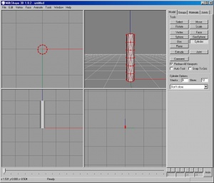
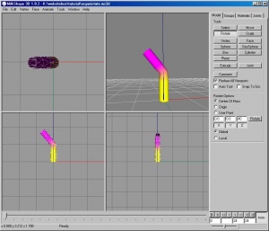
So fire up MilkShape, on the Model tab pick cylinder, set the Stacks to 6, Slices to 12 and use the "Don't Close" option. (Note: This isn't a critical step, but if you use other values your cylinder will look different than mine). Then go to the Face->Smooth All menu item to get rid of the black and show a smooth texture. If your cylinder is not centered over the origin with one end on the ground, use Move to place it so.
Your mesh should look like this one:
Next, we will add two joints. One will be at the bottom and we will call it base. In the Model tab, select Joint and click at the origin. Then go to the joints panel and see that there is a joint1 and that it is highlighted. Type "base" in the box next to the Rename button and click on Rename. The name in the list should change to base and the item remain highlighted.
Being highlighted means it is selected, and then the next step will create a joint that is a child of base. Go back to the Model panel, and first we will set the base joint to the origin by using Move and putting 0 0 0 in the position boxes, choosing absolute and then clicking on Move. Since only the new joint is selected, it moves to the origin and the cylinder stays still.
Now click on Joint again and place a second joint in the middle of the cylinder, halfway up. If your click left it placed incorrectly, use the Move button and drag it to the correct spot. Being pretty close will make the animation we do later act the way we expect.
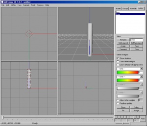
After making the second joint, go to the Joints panel and rename it to "knee". Then, since we are done with our skeleton making, go to the Tools menu and use Zero Joints.
Your creation should look like the screenshot, save your work as a backup:
First, we are going to assign joints the way we learned before, do a simple test animation step and see what happens.
From the Edit menu, Select None. Go to the Joints panel and double-click on the base joint to select it. Then go back to the Model panel and choose the Select button. For the options, click on Vertex and make sure "ignore backfaces" is UNchecked. Now, in the front, back, left or side view, click and drag a box around the lowest three rows of vertices and verify that they all turned red, indicating they are selected. Then go to the joints panel and click on assign.
Now, a clever shortcut. Instead of repeating the previous steps for selecting the rest of the vertices, double-click on the knee joint. Then click on the "SelUnAssigned" button. The remaining vertices, which are unassigned, will be highlighted. Then just click on assign to set them to knee. Use the "Draw vertices with bone colors" checkbox to make sure that the bottom is assigned to the base and the middle row up is assigned to knee.
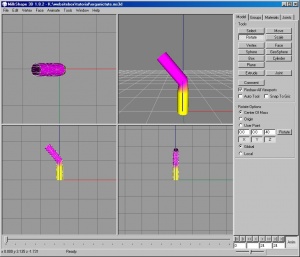
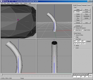
Then do Select None, double click on the knee joint to select it, click on the Anim button, pick Rotate on the Model panel, put 40 in the box above the Z button and click on rotate. If all went well, the results should resemble the image below:
When you look at what we did, you will see that the bend is harsh, folded on one side and indented on the other, like a tube that was bent in a vise. Now, click on Anim again (to go back to modeling mode) and the cylinder will return to the modeled state, because we didn't use Set Keyframe.
Now we are going to use the BoneTool to change the assignments. There is an alternate way to do this in MilkShape, but I don't know how to do it, since I always use the BoneTool method. To start, go back to the Model panel, Select None, then click on the Select button, click and drag to get only the middle row of vertices selected.
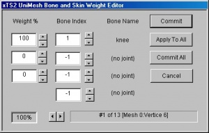
Launch the "Sims2 UniMesh BoneTool" from the Vertex menu. You should see something like what is below:
Notice that there are multiple rows of boxes, which will allow up to four assignments and three weights. You can scroll to individual vertices and set each separately, but since it is difficult to know which vertice number is what one on the screen, and also because we don't really want to do the same thing over again thirteen times, we will assign the whole row the same.
Change the box that says 100 to 50. That cuts the influence of the knee joint to 50%. Notice the bottom left box also changed to 50%, when we are done we will want that to be at exactly 100%. So go to the box directly underneath where we put 50 and put 50 in there.
The total should go to 100%, but the label underneath the word knee will still say "{no joint}". Click the up arrow beside the middle box (Bone Index column) in the second row once, and the value in the box should change to 0 and the name should change to "base".
Now we have set exactly half the influence to the knee (upper) joint and the other half to the base (lower) joint. To complete the assignments, click on "Apply To All" and then on "Commit All".
After Commit All the BoneTool should close. Go to the joints panel and re-enable "Draw vertices with bone colors". Looking carefully at the colors, you should see that in the middle the band that is blended between the bottom and the top will be considerably wider than our original assignment was.
Let's complete the test by repeating our previous anim step. This is what you should see:
Looking at the old bend image and the newer one you should be able to see that the bend is a little smoother, it is still hard, but the indent on the back side of the bend is noticeably smaller. So we are improving things, we just haven't done enough yet.
Make sure than you release the Anim button and save your work. Then, using the same steps we used on the middle row, set the row above the middle to 75% knee, 25% base, and the row above that (second one down) to 85% knee and 15% base.
Then the row below the middle should be set to 75% base, 25% knee and the one below that (second from bottom) to 85% base, 15% knee. This will give us weightings that move from 100% knee on the top row to 100% base on the bottom, but transitioning via partial weighting in the middle.
Select None, double-click on knee in the Joints panel, then rotate like we did at first. Your screen should now resemble the picture below:
So now the bend is spread across pretty much the entire length of the cylinder. While the Anim button is still in and Rotate is selected you can click in the front view and move the mouse from side to side, and the bend will change in real time. Really cool. You can see that when you use an angle more extreme than 45 degrees or so, the steps start to get sharper looking.
So, what can we do with our new tricks?
The first 50%/50% example we used is very close to what we would want to use for a knee joint like we might use on a person or animal. You could improve it further by moving the rows from above and below closer and just using a small influence (10 or 15%) from the opposite end to mimic anatomy more.
Or we could use the part we made pretty much as it is for a flower stem. If we put a sphere on the top (assigned 100% to the knee) and texture it nicely, we could make a small clover plant.
Now, one clover plant is of minimal use, you need a bunch, and you want at least some to be a little different, or it will look like some precise engineering effort. And besides, when we turned Anim off and saved the file, the bends we made disappeared. Fear not, there is an advanced method to making some different subsets bent like you want them.
You make the first one , texture it, and save it for your template file. Then, you go to Anim mode, bend the stem some small amount, then, while still in Anim mode go to file, export, Wavefront Obj and when the warning pops up, just go ahead and click Yes, then save it as something like stem1.obj. Bend it a bit more and export again to stem2.obj. Do this several more times until you think you have enough templates. Bending on the Z axis is enough, because we can rotate these on the Y axis later when we place them.
Now, start your new clover patch with file/new. Don't forget to turn off Anim mode. Import one of your clover models, rename it in the groups panel to something like clover1. This is important, because if it keeps the same object name as the saved file had, it will be replaced when we import the next one.
Select it, rotate it somewhat on the Y axis (use the buttons to restrict rotation to Y) and then use Move to place it somewhere other than on top of the origin. Then import a different clover model, rename to clover2, rotate (as you see fit) and move it to it's own location. Repeat as needed. Void where restricted by law (testing your attention here).
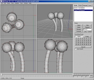
I have a few plants made, and displayed in the scene below, although I didn't texture them because I am lazy and spent a lot of time typing this all in. Someone else can post some textured clovers or whatever, as this technique will work for many other objects, with more joints if desired. You just use the principles of distributing the influences to the degree you want to get the desired effect.
[edit] Questions and Answers
- Custom Sims3 Forums - Visit Custom Sims3 Forums for Questions and Answers
| <<Back | Index | Next>> |
|---|
