Difference between revisions of "Tutorials:Simple Meshing for 3D Studio Max Part 1"
EllaCharm3d (Talk | contribs) (→reviewed for grammar and spelling) |
|||
| (54 intermediate revisions by 2 users not shown) | |||
| Line 1: | Line 1: | ||
{{TS3ModdingHeader}} | {{TS3ModdingHeader}} | ||
| − | {| | + | {| |
|- | |- | ||
| __TOC__ | | __TOC__ | ||
|} | |} | ||
| − | == | + | |
| − | <br/> | + | <br clear="all" /> |
| − | + | == Overview == | |
| − | + | I wanted to write this guide to show you how much you can do with 3D Studio Max. You can easily get lost in this program with its nearly limitless options. This guide will cover a few simple ways of creating an object. It covers the basic, simple steps used to creating more complex Meshes and Textures. Since this is a guide on Simple meshing, UV mapping and textures are also covered. For more detailed guides, continue on to part 2 and 3 of this guide. | |
| + | |||
| + | |||
| + | {| class="nicetable" align="left width=600px" | ||
| + | |- | ||
| + | |'''Note:''' Part 2 & 3 are still in the making and will be posted as soon as they are done. | ||
| + | |} | ||
| + | |||
| + | |||
| + | The way an object is created in this guide is similar to other guides I found for other modeling programs. Even with more complex 3D art scenes, this is still the most common way to shape and mold an object into 3D scenes. 3D Studio Max is capable of much more than this as you may notice during this guide, and its basic features would be explained using the creation of a simple object in this tutorial series. | ||
| + | |||
| + | For the duration of this tutorial series I am using 3D Studio Max 2013, but the steps can also be applied, for the most parts, to older versions of 3ds Max. | ||
| + | <br clear="all" /> | ||
| + | |||
| + | === Learning Curve === | ||
* Creating simple objects in 3D Studio Max. | * Creating simple objects in 3D Studio Max. | ||
* Mapping simple objects in 3D Studio Max. | * Mapping simple objects in 3D Studio Max. | ||
* Importing from and Exporting to MilkShape 3D. | * Importing from and Exporting to MilkShape 3D. | ||
| − | + | ||
| − | + | ||
| − | + | === Things you need to read === | |
* Guides on how to use s3oc/s3pe and/or TSRW, located around various The Sims modding sites (wiki's). | * Guides on how to use s3oc/s3pe and/or TSRW, located around various The Sims modding sites (wiki's). | ||
| − | * Few basic tutorials from 3D Studio Max would not hurt either, even though | + | * Few basic tutorials from 3D Studio Max would not hurt either, even though I explain almost everything, these tutorials can teach you even more. |
| − | + | ||
| − | + | == Creating a reference Scene == | |
| − | + | ||
| − | + | The Sims uses objects in a certain scale, in order to make sure our objects are in the same scale we want to get an exported object into our 3ds Max. In order to do so you must have read up on the guides from the programs you downloaded to export and import objects into The Sims 3. All you need to do is get an object that is more or less similar to what you want to model, we are going to use the same table as most starting tutorials, the infamous ''"TableEndClub"''. | |
| − | + | ||
| − | + | <br clear="all" /> | |
| − | + | ||
| − | + | ||
| − | + | == Importing from MilkShape 3D == | |
| − | + | [[File:Export_Milkshape.jpg|right|250px]] | |
| − | + | The settings are rather simple for this, first of all you don’t need any extra tools for this to work all export option are already included in Milkshape 3D and 3ds Max. When you have the object loaded into Milkshape 3D you simple do the following: ''“File -> Export -> Wavefront OBJ…”'' and save it to your work folder named something like ''“Cloned_low_Detail_Mesh”''. | |
| − | == Creating a reference Scene | + | |
| − | + | ||
| − | The Sims uses objects in a certain scale, in order to make sure our objects are in the same scale we want to get an exported object into our | + | {| class="nicetable" align="left width=600px" |
| − | <br | + | |- |
| − | + | |Hint You can also export\import other formats exporting from and to Milkshape, I suggest playing around with it a little bit. I found .OBJ to be the cleanest format, though some other formats may export more scene related things. | |
| − | + | |} | |
| − | The settings are rather simple for this, first of all you don’t need any extra tools for this to work all export option are already included in Milkshape 3D and | + | <br clear="all" /> |
| − | + | ||
| − | + | [[File:Import_3Ds_Max.jpg|right|250px]] | |
| − | <br/>[[File:Import_3Ds_Max.jpg|right| | + | |
| − | Now for the import part to create our reference scene, this is very easy in | + | Now for the import part to create our reference scene, this is very easy in 3ds Max go to the top left button with the 3Ds max sign on it (it’s the same menu as file in Milkshape). There select ''“Import -> Import”'', now in the next menu navigate to the work folder and select you exported files (this file should just show up as ''“All Formats”'' is on by default, if not select the drop down menu of ''“Files of Type:”'' and select either the ''“.OBJ”'' format or ''“All Formats”'' option). |
| − | + | <br clear="all" /> | |
| − | When proceeding you get a new screen with all kind of options you can select, these settings make up what you import to | + | [[File:Import_Settings_3Ds_Max.jpg|right|250px]] |
| − | + | When proceeding you get a new screen with all kind of options you can select, these settings make up what you import to 3ds Max. We need to pay attention to this screen for a minute to make sure we select all the right options. On the picture I highlighted all options that need to be checked, keep in mind that leaving other switches on might create another end result than we have in this guide. | |
| − | On the picture I highlighted all options that need to be checked, keep in mind that leaving other switches on might create another end result than we have in this guide. | + | |
| − | + | *We want to ''flip ZY-axis'', this is a common setting used for exporting/importing to/from Poser like programs, not checking this may result in a flipped object that you need to rotate to get correct again. | |
| − | We want to ''flip ZY-axis'', this is a common setting used for exporting/importing to/from Poser like programs, not checking this may result in a flipped object that you need to | + | *We also want to import ''Texture coordinates'' and ''Normals (Import from file)''. |
| − | + | ||
| − | We also want to import ''Texture coordinates'' and ''Normals (Import from file)''. | + | |
| − | + | {| class="nicetable" align="left width=600px" | |
| − | + | |-Hint | |
| − | + | |A small word of warning though before we move on, this concerns scaling in 3ds Max, and can make things very complicated if you don’t know how to scale. We are not going to scale the imported objects as I know what I am doing, and I don’t always need to see the end result in 3D up close. The unit conversion from The Sims 3 to 3ds Max is rather harsh by default, and if not scaled the object can’t be viewed up close in 3D very well. If you want to use scaled objects try playing around with the “Unit/Scale” settings on the “OBJ Import Options”, and keep checking in Milkshape how it turns out against the reference size object there. | |
| − | Now we are basically done already, you can look around a little bit now to make sure your import has worked out correctly. | + | |} |
| + | |||
| + | |||
| + | Now we are basically done already, you can look around a little bit now to make sure your import has worked out correctly. | ||
You need to see a solid object now in your perspective viewport (bottom right by default). | You need to see a solid object now in your perspective viewport (bottom right by default). | ||
| − | <br | + | <br clear="all" /> |
| − | + | ||
| − | + | ||
| − | The next step is fairly easy, and is very much needed so you can load this scene with | + | === Saving your first Project as a reference Scene === |
| − | + | [[File:Save_As.jpg|right|250px]] | |
| + | The next step is fairly easy, and is very much needed so you can load this scene with a single click and don’t need to import things again. To do this go to the 3ds Max icon on the top left corner of the program and select ''"Save As -> Save As”.'' Then navigate to your work folder and give it a common name. | ||
| + | |||
Repeat these steps for all Exported meshes you want to replace, so when you are working on something you can always start again from this point if needed. | Repeat these steps for all Exported meshes you want to replace, so when you are working on something you can always start again from this point if needed. | ||
| − | <br | + | <br clear="all" /> |
| − | == Making | + | |
| − | + | ==Making a Model== | |
| − | Making a model is our next step | + | Making a model is our next step. We are going to make a simple model that is more or less the same as the object we imported. We will only make a low-detail one, as the high-detail one is simply the same model but then with added detail levels. Before you start to model you always need to figure out which details you want to go into what model, and which you want molded into your textures. I usually just make flat surfaces on low-detail models; at the most I do raised areas when I want a second level of detail. If this doesn't make any sense to you at this point, don't worry about it. For now we don’t need much detail for doing a low-detail model, so start by loading your low-detail scene so we have an object to scale to. You can directly save this scene under a new name like ''“Modeling_New_end_Table”'' if you want, this creates an extra fail safe. |
| − | + | ||
| − | Before you start to model you always need to figure out which details you want to go into what model, and which you want molded into your textures. I usually just make flat surfaces on low-detail models | + | |
| − | + | ==Creating Simple Objects== | |
| − | For now we don’t need much detail for doing a low-detail model, so start by loading your low-detail scene so we have | + | [[File:Make_Object.jpg|right|250px]] |
| − | + | Simple objects can form the basis of many models, making one or more objects merged with each other can make a whole other object then the primitive basic one was. This is the most common way of modeling to get object made in a quick workflow, but it’s not the most perfect way of making objects. The simple objects often have overlapping areas as the objects are hanging inside each other. For the end result this does not really matter, as you won’t see these overlapping areas. In 3ds Max these objects are called ''“Standard Primitives”'' and can be found on the right hand tool bar if you didn't change the 3ds Max layout. | |
| − | + | <br clear="all" /> | |
| − | + | ||
| − | Simple objects can form the basis of many models, making one or more objects | + | [File:Make_Object_2.jpg|left|250px]] |
| − | + | We are going to start out by using a box to replicate an evenly sized table top; simply select the option “Box” to start making one. You will see a parameters box pop up with some other options, but we won’t be using these. | |
| − | The simple objects often have overlapping areas as the objects are hanging inside each other. For the end result this does not really matter, as you won’t see these overlapping areas. | + | |
| − | + | <br clear="all" /> | |
| − | In | + | |
| − | <br/> | + | [[File:Make_Object_3.jpg|right|250px]] |
| − | We are going to start out by using a box to | + | You can now click in an active viewport to create your box around 2 axes, after doing the 2 axes you will be able to set a 3rd to create the 3D aspect of the object. |
| − | + | ||
| − | You will | + | {| class="nicetable" align="left width=600px" |
| − | <br/> | + | |- |
| − | You can now click in an active | + | |'''Hint''' Objects are created around the Length and Width axis first, regardless of witch viewport you use to make the object in. Keep this in mind when making an object if you intend to use the "Parameters" tab to edit your box after placing it. |
| − | + | |} | |
| − | + | ||
| − | + | ||
| − | Drag it to any height you want (moving the mouse up and down looking at the perspective viewport), just make sure the width and length are the same as I did more or less. It should be more or less the same size as the object we imported. | + | Drag it to any height you want (moving the mouse up and down looking at the perspective viewport), just make sure the width and length are the same as I did more or less. It should be more or less the same size as the object we imported. To clear the box creation mode, right click in the active viewport. |
| − | To clear the box creation mode right click in the active viewport. | + | |
| − | + | Now we are going to move our box to the right position, and then scale it to size a bit more where needed. | |
| − | Now we are going to move our box to the right position, and then scale it to size a bit more | + | |
| − | + | Use the front viewport to select your box if it’s not already selected, pressing the key ''“W”'' makes the move tool active so you can move the box in that front viewport up to the top of the table we have as reference. As you can see I zoomed in to make the final move on top of the bottom line of the reference table top. | |
| − | Use the front viewport to select your box if it’s not already selected, pressing the key ''“W”'' makes the move tool active so you can move the box in that front viewport up to the top of the table we have as reference. | + | |
| − | + | {| class="nicetable" align="left width=600px" | |
| − | As you can see I | + | |- |
| − | + | |'''Hint''' You can also select lines, points and other geometry to move something, just hover over it until your mouse icon changes to 4 arrows. To change the axis constrain press “F8”, although sometimes you need to press it twice to get the correct direction, this way can be faster than finding the tool around the object its control point. | |
| − | + | |} | |
| − | [[File:Make_Object_4.jpg|right| | + | |
| − | + | <br clear="all" /> | |
| − | + | ||
| − | Repeat this action until you have all 4 legs and the use the move tool to fine tune the left position over the reference model. | + | [[File:Make_Object_4.jpg|right|250px]] |
| − | <br/> | + | We will fine-tune the table top later, we first need to rename it and create the legs and other details first. Go to the edit model toolbar and enter the name ''“Table Top”'' as shown. After this, go back to making a box and create a box around a leg of the reference object like you did with the table top. This time to match the height as much as possible as well. Start working from the top viewport and use the perspective view as a reference view. Don’t worry about moving outside of the top of the screen for the height, the mouse button will appear on the bottom again as soon as you scroll out. |
| − | + | ||
| − | Once you release the mouse button a ''“Clone Option”'' menu will pop up, in this menu you need to select the “Copy” to object function and name the object ''“leg_2”''. | + | Repeat this action until you have all 4 legs and the use the move tool to fine-tune the left position over the reference model. |
| − | + | ||
| + | <br clear="all" /> | ||
| + | [[File:Make_Object_5.jpg|right|250px]] | ||
| + | You can select your first leg and press the ''“Shift”'' key while dragging it across the screen to another leg. Once you release the mouse button a ''“Clone Option”'' menu will pop up, in this menu you need to select the “Copy” to object function and name the object ''“leg_2”''. | ||
| + | |||
Rename the one leg you haven’t renamed yet if you cloned them all, or rename them all if you made separate boxes. Then quickly scale them a little bit if needed and also move them a bit. For scaling use the ''“Tools -> Scale”'' menu, it works the same as the move tool. Or find the button on the top tool bar 2 icons over from the move tool to the right. | Rename the one leg you haven’t renamed yet if you cloned them all, or rename them all if you made separate boxes. Then quickly scale them a little bit if needed and also move them a bit. For scaling use the ''“Tools -> Scale”'' menu, it works the same as the move tool. Or find the button on the top tool bar 2 icons over from the move tool to the right. | ||
| − | + | ||
You can see now we already create a large portion of the table in a matter of seconds (if you don’t count the reading part, in my case writing ….). | You can see now we already create a large portion of the table in a matter of seconds (if you don’t count the reading part, in my case writing ….). | ||
| − | <br/>[[File:Make_Object_6.jpg|right| | + | |
| − | I don’t want a center piece like this table with a drawer in it, | + | <br clear="all" /> |
| − | + | [[File:Make_Object_6.jpg|right|250px]] | |
| − | You should be able to do this without help from here on out, so I’m going more into the creating 3 boards out of the one board. You just learned how to drag clone an object making the legs | + | I don’t want a center piece like this table with a drawer in it, I want to have 3 boards spread from bottom to top instead. To get this done we are going to start by making a box that is going to make up the same size later as the bottom board the reference object has. |
| − | + | ||
| + | You should be able to do this without help from here on out, so I’m going more into the creating 3 boards out of the one board. You just learned how to drag clone an object making the legs. This time we are going to use another tool to make all the copies at once at the place we want them to be. | ||
| + | |||
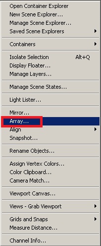
Create, scale and move a box to form the bottom board and call it ''“Board”'', then use the ''“Tools -> Array”'' tool and see the new configuration window pop up. | Create, scale and move a box to form the bottom board and call it ''“Board”'', then use the ''“Tools -> Array”'' tool and see the new configuration window pop up. | ||
| − | + | ||
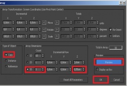
| − | Again select the ''“Copy”'' option and now let’s duplicate this thing around an axis for a set amount of centimeters (in my case). Click the ''“3D Array Dimensions”'' and enter a count of 3 then set a value of ''“0 | + | Again select the ''“Copy”'' option and now let’s duplicate this thing around an axis for a set amount of centimeters (in my case). Click the ''“3D Array Dimensions”'' and enter a count of 3 then set a value of ''“0.55”'' on the Z–Axis, now click ''"Preview"'' and watch what happens. If you like what you see click ''“Ok”'' if not fine-tune it to your taste and click ''“Ok”''. |
| − | + | ||
| − | Now that we have the object we want we can start grouping and fine-tuning the scaling where needed. | + | |
| − | + | [[File:Make_Object_7.jpg|right|250px]] | |
| − | If you did it all correct you will get the following preview in your perspective view. | + | |
| − | + | <br clear="all" /> | |
| + | |||
| + | [[File:Make_Object_8.jpg|right|250px]] | ||
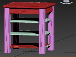
| + | Now that we have the object we want we can start grouping and fine-tuning the scaling where needed. If you did it all correct you will get the following preview in your perspective view. | ||
| + | |||
Colors may vary, as they are generated randomly when making objects. | Colors may vary, as they are generated randomly when making objects. | ||
| − | <br/>[[File: | + | |
| − | + | <br clear="all" /> | |
| − | + | ||
| − | + | == Grouping simple objects == | |
| − | + | [[File:Object_Grouping.jpg|right|alt text|250px]] | |
| − | With this element, or modifier | + | [[File:Object_Grouping_2.jpg|right|alt text|250px]] |
| − | + | To create a solid object with matching sizes we need to take one element and convert it to something workable; in this case it’s going to be an element called ''“Editable Polygon”''. | |
| + | With this element, or modifier, you can modify the object on the area you want to. You can merge other objects into your mesh to create one solid Group/Mesh to export or texture map. | ||
| + | |||
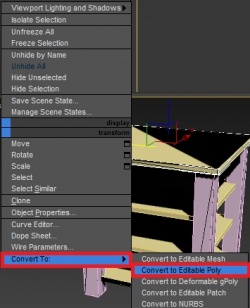
To do this select one object, let’s start with the table top for example. And right click in your active viewport to open a drop down menu, and then select ''“Convert to Editable Poly”'' from it and watch the edit toolbar change. Once you done this rename your object to ''“End_Table”'', and enter the vertex select level. | To do this select one object, let’s start with the table top for example. And right click in your active viewport to open a drop down menu, and then select ''“Convert to Editable Poly”'' from it and watch the edit toolbar change. Once you done this rename your object to ''“End_Table”'', and enter the vertex select level. | ||
| − | <br/>[[File: | + | |
| − | Select one of the top vertexes and start moving it around to match that side of the reference object, keep selecting and moving around vertexes until you table top is the same size and shape as the reference object. | + | <br clear="all" /> |
| − | + | ||
| − | We will merge another object to this | + | [[File:Move_Vertex.jpg|right|alt text|250px]]<br/> |
| − | + | Select one of the top vertexes and start moving it around to match that side of the reference object, keep selecting and moving around vertexes until you table top is the same size and shape as the reference object. We will merge another object to this once we have the correct size for this object. | |
| − | Now you only need 2 viewports to make this object the correct size, but feel free to use this stage to test around with the movements in | + | |
| − | + | ||
| − | I found the movement to be slightly off from most modeling tools | + | Now you only need 2 viewports to make this object the correct size, but feel free to use this stage to test around with the movements in 3ds Max a bit. As you can see in the screenshot I attached everything and then moved around the geometry. |
| − | <br/>[[File:Object_Grouping_3.jpg|right|alt text| | + | |
| − | Now let’s merge a leg to our table top and make that the correct size. | + | I found the movement to be slightly off from most modeling tools I used, I had a few little issues with the perspective viewport but I learned to love the way you move around in 3ds Max its gives a nice and smooth handling. |
| − | + | ||
| − | You may have noticed that the reference objects has slightly sloped legs, we are not going to replicate that, and we want the top shape of the legs and nothing else. | + | <br clear="all" /> |
| − | + | ||
| + | [[File:Object_Grouping_3.jpg|right|alt text|250px]] | ||
| + | Now let’s merge a leg to our table top and make that the correct size. You may have noticed that the reference objects has slightly sloped legs, we are not going to replicate that, and we want the top shape of the legs and nothing else. | ||
| + | |||
There are 2 ways of making this merge happen, both are done in the objects editable mesh settings under the tab ''“Edit Geometry”'' the options we are looking for is ''“Attach”'' and ''“Attach List”'' (the box behind it). | There are 2 ways of making this merge happen, both are done in the objects editable mesh settings under the tab ''“Edit Geometry”'' the options we are looking for is ''“Attach”'' and ''“Attach List”'' (the box behind it). | ||
| − | + | ||
| − | The first is selection based you can use a viewport to select the object you want to merge with. The second is based on a list | + | The first is selection based you can use a viewport to select the object you want to merge with. The second is based on a list, you get a list of object names and select our leg from that menu to merge with your table top. |
| − | + | ||
It’s up to how you merge the leg(s) to your object, proceed with the leg you merge to match the top size of the reference legs. | It’s up to how you merge the leg(s) to your object, proceed with the leg you merge to match the top size of the reference legs. | ||
| − | + | ||
| − | Once you are done with the one leg | + | [[File:Object_Grouping_4.jpg|right|alt text|250px]] |
| − | + | Once you are done with the one leg repeat this around for all legs. | |
| − | + | ||
| − | + | ||
| + | {| class="nicetable" align="left width=600px" | ||
| + | |- | ||
| + | |'''Hint''' Is a certain object in your way? Select that object and use the right click menu on an active viewport to use the option “Hide Selection”. The object is now hidden until you unhide it true from this same menu. | ||
| + | |} | ||
| + | |||
| + | |||
Now you can use the same learned craft to complete the initial object, attach all remaining objects and scale them to size after that, if you did the same as me the next picture will be more or less the same with the reference object hidden. | Now you can use the same learned craft to complete the initial object, attach all remaining objects and scale them to size after that, if you did the same as me the next picture will be more or less the same with the reference object hidden. | ||
| − | + | ||
| − | We are almost done as well with this object we need to prepare it for texture mapping and exporting. | + | We are almost done as well with this object we need to prepare it for texture mapping and exporting. To finish the object we are first going to rename it to ''“Group_01”'' and then we want to add a few extra lines. |
| − | + | ||
| − | To finish the object we are first going to rename it to ''“Group_01”'' and then we want to add a few extra lines. | + | <br clear="all" /> |
| − | <br/> | + | |
| − | + | {| class="nicetable" align="left width=600px" | |
| − | <br/> | + | |- |
| − | As you can see reference object has some extra diagonal lines in the object. | + | |'''Note:''' This next step is not really needed for simple objects with low detail like this one, 3D Studio max has an automated tessellation when using "Editable Mesh" objects. Just for the sake of showing the option I used it in the guide. The object will just work and show up perfectly without it. |
| − | + | |} | |
| − | We are going to do this | + | |
| − | + | ||
| + | <br clear="all" /> | ||
| + | |||
| + | [[File:Object_Grouping_5.jpg|right|alt text|250px]]<br/> | ||
| + | |||
| + | As you can see the reference object has some extra diagonal lines in the object. We are going to do this too, it’s a simple operation called ''“Tessellate”'' and can be found in the ''“Edit Geometry”'' tab. | ||
| + | |||
For this option to show up as usable you need to be in ''“Face”'', ''“Element”'' or ''“Polygon”'' selection mode and you need to select all Faces/Elements/Polygons (''"Ctrl+A"'') for it. | For this option to show up as usable you need to be in ''“Face”'', ''“Element”'' or ''“Polygon”'' selection mode and you need to select all Faces/Elements/Polygons (''"Ctrl+A"'') for it. | ||
| − | + | ||
| − | The box behind it is the one we want, depending on your version of | + | The box behind it is the one we want, depending on your version of 3ds Max the menu may be different, but option should be the same. Set the same as my screenshot to get a similar end-result. |
| − | <br/> | + | |
| + | <br clear="all" /> | ||
| + | |||
| + | [[File:Object_Grouping_6.jpg|right|250px]] | ||
The end result should be similar to the following, if you have the same as me move on to the texture mapping part of this guide. | The end result should be similar to the following, if you have the same as me move on to the texture mapping part of this guide. | ||
| − | + | ||
| − | Be sure to make a saved scene of the progress so far. | + | Be sure to make a saved scene of the progress so far. Next up is mapping the sides to make a wood grain fit in The Sims 3. |
| − | + | ||
| − | Next up is mapping the sides to make a wood grain fit in The Sims 3. | + | |
<br/><br/> | <br/><br/> | ||
| − | = | + | |
| − | + | <br clear="all" /> | |
| − | + | ||
| − | + | == Creating a simple mapping == | |
| − | The one we are going to use now is called ''“Unwrap UWV”''. This modifier can select object faces and | + | To create a simple mapping to form the basis of our texture, from here on out you can do without our reference object. You can either delete it or keep it on hide for the entire process. In 3ds Max you have a ton of modifiers to pick from to shape and mold the outcome of your model. I haven’t tested all of them yet in combination with The Sims, but I reckon that those making a solid object will work as long as you collapse them into the Mesh. |
| − | + | ||
| − | Let’s get to it and assign this modifier to our object, look at the screenshot | + | [[File:Object_Mapping.jpg|right|alt text|250px]] |
| − | <br | + | [[File:Object_Mapping_2.jpg|right|alt text|250px]] |
| − | First we need to setup rendering and bitmap sizes, in order for this to come out properly we need every bitmap size to match the exported examples. The size we want is 256Wx512H Pixels, we need to set this both to render settings and to bitmap size in the “Edit UWVs”. For the “Render Setup” press “F10” (see screenshot where to find the settings you need to change), as you can see I set a render preset as well. If you do this now you won’t have to do this later. | + | The one we are going to use now is called ''“Unwrap UWV”''. This modifier can select object faces and vertices in order to create a texture mapping that suits you. The way this is being done is much like the UV mappers currently used for modding The Sims. The plus side here is that you can create simple base textures as well, this saves you using other programs to create ''“fake”'' shadows and highlights. |
| − | + | ||
| − | + | Let’s get to it and assign this modifier to our object, look at the screenshot for where to find it. Now in this mode, it has similar button to the editable mesh one, but as you can see only 3 selection mode, and a grey 4th if you're using 2013. | |
| − | + | <br clear=all> | |
| − | + | ||
| − | <br | + | [[File:Object_Mapping_3.jpg|right|alt text|250px]] |
| + | |||
| + | First we need to setup rendering and bitmap sizes, in order for this to come out properly we need every bitmap size to match the exported examples. The size we want is 256Wx512H Pixels, we need to set this both to render settings and to bitmap size in the ''“Edit UWVs”''. For the “Render Setup” press ''“F10”'' (see screenshot where to find the settings you need to change), as you can see I set a render preset as well. If you do this now you won’t have to do this later. Now close the setup menu when done. | ||
| + | |||
| + | |||
| + | {| class="nicetable" align="left width=600px" | ||
| + | |- | ||
| + | |'''Note:''' The render preset is only needed for 3ds Max 2013, 'cause else you can’t render the Occlusion mapping that we need. Don’t worry about loading things at this point we have our backup object already and are going to save this scene later under a new name. | ||
| + | |} | ||
| + | |||
| + | |||
| + | <br clear=all> | ||
| + | [[File:Object_Mapping_4.jpg|right|alt text|250px]] | ||
Go into the face selection and select all faces on the object using ''“Ctrl+A”'', once this is done click the ''“Open UV Editor”'' box and be amazed by a new epic window (2011 and up got major improvements here, screenshots may be of from here on out, but option names are still the same). Now we need to do 2 things, as you can see we have 1 big red square now. We need to flatten this mapping a little so we can work with it, and then apply a texture to see how our grains are turning out. | Go into the face selection and select all faces on the object using ''“Ctrl+A”'', once this is done click the ''“Open UV Editor”'' box and be amazed by a new epic window (2011 and up got major improvements here, screenshots may be of from here on out, but option names are still the same). Now we need to do 2 things, as you can see we have 1 big red square now. We need to flatten this mapping a little so we can work with it, and then apply a texture to see how our grains are turning out. | ||
| − | + | ||
To do this go to ''“Option -> Preferences”'' on the ''“Edit UVWs”'' screen, or press ''“Ctrl+O”''. Now you will see a settings window where we are going to change a few things before we move on. We need to set the bitmap size here we want to work with, so we can scale our mapping accordingly. I also turned on the grid with black lines and a grey background, and told the editor to tile my bitmaps. | To do this go to ''“Option -> Preferences”'' on the ''“Edit UVWs”'' screen, or press ''“Ctrl+O”''. Now you will see a settings window where we are going to change a few things before we move on. We need to set the bitmap size here we want to work with, so we can scale our mapping accordingly. I also turned on the grid with black lines and a grey background, and told the editor to tile my bitmaps. | ||
| − | <br/> | + | |
| − | With all faces still selected go to ''“Mapping -> Flatten Mapping”'', now a settings box will open here I only changed the ''“Face Angle Threshold”'' to a value of ''“75 | + | <br clear="all" /> |
| − | <br | + | [[File:Object_Mapping_5.jpg|right|alt text|250px]] |
| − | + | With all faces still selected go to ''“Mapping -> Flatten Mapping”'', now a settings box will open here I only changed the ''“Face Angle Threshold”'' to a value of ''“75.0”'' this created for me a proper base mapping to work with. If you like to mess around with the setting to create your own mapping, feel free to do so. ''(Sorry about the 512x512 background I failed)'' | |
| − | + | ||
| − | + | <br clear="all" /> | |
| − | + | ||
| + | == Editing that simple mapping == | ||
| + | [[File:Object_Mapping_6.jpg|right|alt text|250px]] | ||
| + | I moved the easy to map areas to the top by the all getting its own part on the texture mapping. | ||
The screenshot should show you all option on how to get the arrangement I made. | The screenshot should show you all option on how to get the arrangement I made. | ||
| − | + | Also, I moved the legs and sides of the tables to the bottom of the mapping, I'll arrange them later to match the wood grains. | |
| − | Also I moved the legs and sides of the tables to the bottom of the mapping, | + | |
| − | + | ||
You can see the objects themselves are spaced from each other, but in between the groups are still large empty areas. | You can see the objects themselves are spaced from each other, but in between the groups are still large empty areas. | ||
| − | |||
This will sort now as well, and we will flip over some faces to match the wood grains we need. | This will sort now as well, and we will flip over some faces to match the wood grains we need. | ||
| − | |||
Also I kept the feet ends out of the bitmap for now, as you won’t be seeing much of these anyways. | Also I kept the feet ends out of the bitmap for now, as you won’t be seeing much of these anyways. | ||
| − | + | ||
| − | + | ||
| − | <br/> | + | {| class="nicetable" align="left width=600px" |
| + | |- | ||
| + | |'''Hint:''' If you do need to rotate check the “Quick Transform” tab to the right. | ||
| + | |} | ||
| + | |||
| + | <br clear="all" /> | ||
| + | |||
| + | [[File:Object_Mapping_7.jpg|right|alt text|250px]] | ||
Ok now for the grain alignments, let’s say we have a wood texture with grains going from the top of the map to the bottom. | Ok now for the grain alignments, let’s say we have a wood texture with grains going from the top of the map to the bottom. | ||
| − | |||
For the table top and boards this isn’t a big issue, but for all sides and legs it is. | For the table top and boards this isn’t a big issue, but for all sides and legs it is. | ||
| − | |||
If you look at our alignment the feet are currently having the grains from left to right projected, so we need to rotated them 90 degrees to get the pattern to go from top to bottom (read the hint above, don’t worry about moving them outside the texture map). | If you look at our alignment the feet are currently having the grains from left to right projected, so we need to rotated them 90 degrees to get the pattern to go from top to bottom (read the hint above, don’t worry about moving them outside the texture map). | ||
| − | + | ||
Now the sides are a little bit more complicated, the easy way is to select a part of the table top in your 3D viewport, and then looking in the editor how the face is turned. | Now the sides are a little bit more complicated, the easy way is to select a part of the table top in your 3D viewport, and then looking in the editor how the face is turned. | ||
| − | + | When you see the grain is going through that face you need to make the side align the same way. | |
| − | When you see the grain is going | + | |
| − | + | ||
Bluntly said on the texture map you want the left and right side to be in the same orientation as the top/bottom half. | Bluntly said on the texture map you want the left and right side to be in the same orientation as the top/bottom half. | ||
| − | |||
This way the grain falls over the edge into the bottom section like as if it was a proper board. | This way the grain falls over the edge into the bottom section like as if it was a proper board. | ||
| − | |||
In the next picture you can see the rotated faces as a reference to how you might want it ''(yes I changed the line colors for this ><)''. | In the next picture you can see the rotated faces as a reference to how you might want it ''(yes I changed the line colors for this ><)''. | ||
| − | <br/><br/> | + | |
| + | <br clear="all" /> | ||
| + | |||
| + | [[File:Object_Mapping_8.jpg|right|alt text|250px]]<br/> | ||
Now we have the objects aligned we need to scale them to match an equal size to what we have on the object. Currently everything is kind of torn slightly too much to the map size. You can see the table top is not square anymore, we want to slightly change this back same goes for any parts that are outside the dark lines square that makes up the texture map. | Now we have the objects aligned we need to scale them to match an equal size to what we have on the object. Currently everything is kind of torn slightly too much to the map size. You can see the table top is not square anymore, we want to slightly change this back same goes for any parts that are outside the dark lines square that makes up the texture map. | ||
| − | |||
Every single face needs to be inside the texture map when you are finished. | Every single face needs to be inside the texture map when you are finished. | ||
| − | + | The next picture is a view of how the texture map should look once you are done scaling things, the size doesn’t have to be spot on as mine, but do try to fill up most of the texture mapping areas to ensure you got as much as possible detail on each part you created. | |
| − | The next picture is a view of how the texture map should look once you are done scaling things, the size doesn’t have to be spot on as mine, but do try to fill up most of the texture mapping | + | |
| − | + | ||
I used the table top sizes to scale my sides that I rotated, and I increased the leg size by the amount of spare space I had left after moving around the table tops. | I used the table top sizes to scale my sides that I rotated, and I increased the leg size by the amount of spare space I had left after moving around the table tops. | ||
| − | |||
And in the spare spots I made the feet top and bottoms fit, also scaling them up a little bit more to fill up the holes. | And in the spare spots I made the feet top and bottoms fit, also scaling them up a little bit more to fill up the holes. | ||
| + | |||
| + | <br clear="all" /> | ||
| + | |||
| + | == Baking simple map textures == | ||
| + | [[File:Object_Mapping_9.jpg|right|alt text|250px]] | ||
| + | Now in order to create a good object we need textures to replace the one exported from your project. For this to work properly we first need to make simple extractions of our UVW mapping we just made; make sure to open the ''“Open UV Editor”'' option if it’s not still opened. | ||
| + | |||
| + | |||
| + | We can create simple paint backgrounds form this menu that provides a rather good basis for our final texture. To do this select the option ''“Tools -> Render UVW Template”'', and take note of the new window that opens up.In the screenshot you can see the option I used to render all 3 maps from the drop down menu ''“Mode”'' under the ''“Fill”'' tab. Render and save all 3 option ''“Solid”'', ''“Normal”'' and ''“Shaded”'' and name them something corresponding (I saved them all in .TIF 16-bit format to convert them into .dds later on in Photoshop and no, that is not our mapping that shows)''. | ||
| + | |||
| + | |||
| + | {| class="nicetable" align="left width=600px" | ||
| + | |- | ||
| + | |'''Note:''' These basic texture mappings are the most basic there are, the normal mapping used here is far from the best normal mapping you can get on the object. But like many things these form a basis for the object in most scenarios. This table might not be the best example for this, but on more complex models you may get better results using the texture baking explained below. | ||
| + | |} | ||
| + | |||
| + | |||
| + | Now the harder part of making a material to assign to the object and making the final mappings we need, we need a shaded mapping with grey and white colors for the main map, and we need another Specular Map from 3ds Max with loads of white areas and only few shaded spots. | ||
| + | |||
| + | In earlier version of Studio Max this was easier to get done, for my 2013 part of the guide I will have to save my scene under another name again and do the material assignment and assembly part. I suggest you do the same for the sake of keeping a clean mesh. Since the object is done and mapped you can export it and work on the textures in other programs if needed. | ||
| + | |||
| + | Once you save your scene press the ''“M”'' key and if in 2012 and higher try not to get overwhelmed by option and cool looks. For this part we are going to build up our material starting to make a shaded base texture from the mappings we just saved. | ||
| + | |||
| + | |||
| + | {| class="nicetable" align="left width=600px" | ||
| + | |- | ||
| + | |'''Note:''' The material editor has changed a lot since 2010, if you're using an earlier version and do not see any option you can relate to, make sure to read up on the tutorials from 3ds Max itself to get into this a little more I’m not using any advance option you cannot learn in less than 5 minutes reading. The names of the option are still the same but are not nearly the same to access as in 2013. | ||
| + | |} | ||
| + | |||
| + | <br clear=all> | ||
| + | [[File:Object_Baking.jpg|right|alt text|250px]] | ||
| + | [[File:Object_Baking_2.jpg|right|alt text|250px]] | ||
| + | Right click in the material editor for max 2013 and select standard material from the drop down menu. Once you see this material in the editor, double click the material in the editor to make a new window show up, click the darkened square behind the name ''“Diffuse”'' and select ''“Bitmap”'' from the menu that pops up next. Then browse to the texture we saved before and select the solid map you saved. | ||
| + | |||
| + | Repeat these steps to input your Shaded map into the ''“Specular”'' slot and the Normal map into the ''“Specular Level”'' slot. You can also swap the Normal and Shaded map, or play around a bit with it, but I found this to give an average end result that was to my liking. | ||
| + | |||
| + | Now give it the following numbers for both ''“Specular Level”'' and ''“Glossiness”'': 15/25. | ||
| + | |||
| + | Now make sure your object is selected and right click the material in the material editor and select ''“Assign Material to Selection”'' from the drop down menu. | ||
| + | |||
| + | This should already be the base color for your object; this color is later on replaced by the Mask mapping with a pattern from The Sims 3. You might think it’s a bit light, but these mappings are meant to be edited in Photoshop later on. Even though you can use these methods I’m showing to create really nice mappings I still like to use Photoshop for the final edits and shades. | ||
| + | |||
| + | <br clear="all" /> | ||
| + | [[File:Object_Baking_3.jpg|right|alt text|250px]] | ||
| + | [[File:Object_Baking_4.jpg|right|alt text|250px]] | ||
| + | Now we are going to bake this texture into a new texture that can be exported to Photoshop and later on import as a texture map. I’m going to leave the parts outside of 3D Studio Max up to you to do, as the tutorials written to import stuff in The Sims 3 cover this a lot smoother then I would ever be able to. | ||
| + | |||
| + | Now how to bake these 3 maps into the one mapping you see now in your 3d viewport. Go to ''“Render -> Render to Texture”'' or press the key ''“0”'' and again make sure your object is selected. | ||
| + | |||
| + | Check out the following screenshot to see if your settings are matching mine for the easy way of baking the texture. | ||
| + | |||
| + | In the ''“Output”'' Tab click the ''“Add..”'' button and select ''“Ambient Occlusion (MR)”'' from the menu make sure to replicate all settings and also click the ''“…”'' behind ''“File Name and Type”'' to select a save location and format for you file ''(I again used .TIF)''. | ||
| + | |||
| + | Also make sure the texture is assigned to a ''“Target Map Slot”'' ''(Ambient Color in this case)'' And set the bitmaps to 256x512, repeat this process for all maps you can add using the ''“Add”'' Button try to match them to a corresponding slot like with the ambient map ''(although it’s not need to do so it prevents an error message from popping up that I’m not showcasing)''. Click on ''“Render”'' once you are done. | ||
| + | |||
| + | To check the results im going to change my material now with these maps, and add the ''“Oclussion”'' map to the Diffuse color the ''“Specular”'' to the specular color and the ''“Shadows”'' to the specular level map. You can see my end result when I rendered my picture. | ||
| + | |||
| + | <br clear="all" /> | ||
| + | |||
| + | ====Preview==== | ||
| + | [[File:Object_Baking_5.jpg|right|alt text|250px]] | ||
| + | Not bad for a start I would say, play around with these settings a little to see what suits you best, I’m going to merge these mappings we made to create a final mapping. The light one can be used as Specular mapping. I’m also using Photoshop to contrast another baked texture we made to use as a base mapping. This also because I’m not totally happy yet with my baked end results in 2013. | ||
<br/><br/> | <br/><br/> | ||
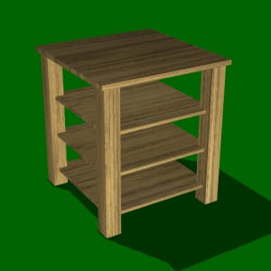
| − | ==== | + | But for now texture and mapping is done, this object is ready for The Sims 3; we need to clean up the scene by converting our object to an ''"Editable Mesh"''. And save the scene again under a common name, exporting like this should not cause any issue using the same settings as import from the first Part of this guide. |
| + | |||
| + | <br clear="all" /> | ||
| + | ====Export==== | ||
| + | [[File:Object_Baking_6.jpg|right|alt text|250px]] | ||
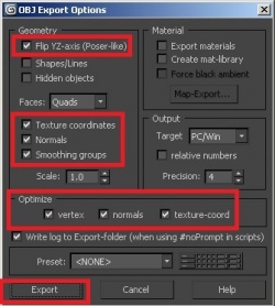
| + | To export from here, select your object and use the ''“File -> Export -> Export Selected”'' option to export the selected object. The screenshot will once again show you the setting you need make it work with Milkshape. | ||
| + | |||
| + | From here on out you should be able to import this object into The Sims 3 tools you are using, and finalize/optimize the textures as well to import them to The Sims 3. | ||
| + | |||
| + | |||
| + | {| class="nicetable" align="left width=600px" | ||
| + | |- | ||
| + | |'''Note:''' The process of baking textures is rather easy this way, sometimes the mappings don't get rendered properly. Some maps that are saved may even be black, the reason for this is cause we didn't bother using a light source for this guide, and 'cause I didn't go into the alternate setting too much. Learning on how to bake properly is a process of trial and error, the only way to get the textures you want is to try out settings and view the results. In later guides 'i will try to explain a bit more on this option, there are many ways to hide details into your Mesh textures this way. | ||
| + | |} | ||
| + | |||
| + | |||
| + | [[File:Object_Baking_7.jpg|right|alt text|250px]] | ||
| + | |||
| + | <br clear="all" /> | ||
| + | |||
| + | == Afterword == | ||
| + | [[File:Object_Baking_8.jpg|right|alt text|300px]] | ||
| + | I hope you enjoyed this simple guide and I hope this guide wasn’t too simple for your liking. Please feel free to experiment more with texture baking and mapping. 3ds Max offers an endless amount of options in this area, and I am only still learning the greatness of texture mapping and baking. | ||
| + | |||
| + | The next Guide in this series will cover advanced modeling and texture mapping, although again the texture mapping may seems rather newbies, it’s an easy way to show people how to work around some areas in 3D Studio Max that they may have done slightly different in other programs. Anyways, it’s been fun writing this, and I hope I taught some people a couple of things. | ||
| + | |||
| + | I hope to see you on my next tutorial on meshing in 3ds Max. | ||
| + | |||
| + | |||
| + | {| class="nicetable" align="left width=600px" | ||
| + | |- | ||
| + | |'''Note:''' The end result is the final look for the object in TSRW, the mappings we made during this guide I mixed up in Photoshop to get a similar looking result as the exported textures. I saved the new once to corresponding correct .dds format textures and imported the lot as a low detail model. Total workflow time without typing this guide is around 20minutes and with that I even struggled still with the UV and Texture mappings. | ||
| + | |} | ||
Latest revision as of 18:05, 29 October 2012
| Tutorials by Category | |
|---|---|
|
CAS | Patterns | Objects | Building | Worlds | Modding | Modding Reference |
|
[edit] Overview
I wanted to write this guide to show you how much you can do with 3D Studio Max. You can easily get lost in this program with its nearly limitless options. This guide will cover a few simple ways of creating an object. It covers the basic, simple steps used to creating more complex Meshes and Textures. Since this is a guide on Simple meshing, UV mapping and textures are also covered. For more detailed guides, continue on to part 2 and 3 of this guide.
| Note: Part 2 & 3 are still in the making and will be posted as soon as they are done. |
The way an object is created in this guide is similar to other guides I found for other modeling programs. Even with more complex 3D art scenes, this is still the most common way to shape and mold an object into 3D scenes. 3D Studio Max is capable of much more than this as you may notice during this guide, and its basic features would be explained using the creation of a simple object in this tutorial series.
For the duration of this tutorial series I am using 3D Studio Max 2013, but the steps can also be applied, for the most parts, to older versions of 3ds Max.
[edit] Learning Curve
- Creating simple objects in 3D Studio Max.
- Mapping simple objects in 3D Studio Max.
- Importing from and Exporting to MilkShape 3D.
[edit] Things you need to read
- Guides on how to use s3oc/s3pe and/or TSRW, located around various The Sims modding sites (wiki's).
- Few basic tutorials from 3D Studio Max would not hurt either, even though I explain almost everything, these tutorials can teach you even more.
[edit] Creating a reference Scene
The Sims uses objects in a certain scale, in order to make sure our objects are in the same scale we want to get an exported object into our 3ds Max. In order to do so you must have read up on the guides from the programs you downloaded to export and import objects into The Sims 3. All you need to do is get an object that is more or less similar to what you want to model, we are going to use the same table as most starting tutorials, the infamous "TableEndClub".
[edit] Importing from MilkShape 3D
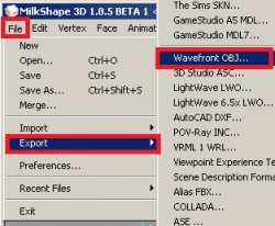
The settings are rather simple for this, first of all you don’t need any extra tools for this to work all export option are already included in Milkshape 3D and 3ds Max. When you have the object loaded into Milkshape 3D you simple do the following: “File -> Export -> Wavefront OBJ…” and save it to your work folder named something like “Cloned_low_Detail_Mesh”.
| Hint You can also export\import other formats exporting from and to Milkshape, I suggest playing around with it a little bit. I found .OBJ to be the cleanest format, though some other formats may export more scene related things. |
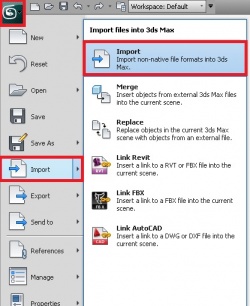
Now for the import part to create our reference scene, this is very easy in 3ds Max go to the top left button with the 3Ds max sign on it (it’s the same menu as file in Milkshape). There select “Import -> Import”, now in the next menu navigate to the work folder and select you exported files (this file should just show up as “All Formats” is on by default, if not select the drop down menu of “Files of Type:” and select either the “.OBJ” format or “All Formats” option).
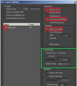
When proceeding you get a new screen with all kind of options you can select, these settings make up what you import to 3ds Max. We need to pay attention to this screen for a minute to make sure we select all the right options. On the picture I highlighted all options that need to be checked, keep in mind that leaving other switches on might create another end result than we have in this guide.
- We want to flip ZY-axis, this is a common setting used for exporting/importing to/from Poser like programs, not checking this may result in a flipped object that you need to rotate to get correct again.
- We also want to import Texture coordinates and Normals (Import from file).
| A small word of warning though before we move on, this concerns scaling in 3ds Max, and can make things very complicated if you don’t know how to scale. We are not going to scale the imported objects as I know what I am doing, and I don’t always need to see the end result in 3D up close. The unit conversion from The Sims 3 to 3ds Max is rather harsh by default, and if not scaled the object can’t be viewed up close in 3D very well. If you want to use scaled objects try playing around with the “Unit/Scale” settings on the “OBJ Import Options”, and keep checking in Milkshape how it turns out against the reference size object there. |
Now we are basically done already, you can look around a little bit now to make sure your import has worked out correctly.
You need to see a solid object now in your perspective viewport (bottom right by default).
[edit] Saving your first Project as a reference Scene
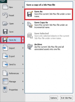
The next step is fairly easy, and is very much needed so you can load this scene with a single click and don’t need to import things again. To do this go to the 3ds Max icon on the top left corner of the program and select "Save As -> Save As”. Then navigate to your work folder and give it a common name.
Repeat these steps for all Exported meshes you want to replace, so when you are working on something you can always start again from this point if needed.
[edit] Making a Model
Making a model is our next step. We are going to make a simple model that is more or less the same as the object we imported. We will only make a low-detail one, as the high-detail one is simply the same model but then with added detail levels. Before you start to model you always need to figure out which details you want to go into what model, and which you want molded into your textures. I usually just make flat surfaces on low-detail models; at the most I do raised areas when I want a second level of detail. If this doesn't make any sense to you at this point, don't worry about it. For now we don’t need much detail for doing a low-detail model, so start by loading your low-detail scene so we have an object to scale to. You can directly save this scene under a new name like “Modeling_New_end_Table” if you want, this creates an extra fail safe.
[edit] Creating Simple Objects
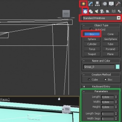
Simple objects can form the basis of many models, making one or more objects merged with each other can make a whole other object then the primitive basic one was. This is the most common way of modeling to get object made in a quick workflow, but it’s not the most perfect way of making objects. The simple objects often have overlapping areas as the objects are hanging inside each other. For the end result this does not really matter, as you won’t see these overlapping areas. In 3ds Max these objects are called “Standard Primitives” and can be found on the right hand tool bar if you didn't change the 3ds Max layout.
[File:Make_Object_2.jpg|left|250px]] We are going to start out by using a box to replicate an evenly sized table top; simply select the option “Box” to start making one. You will see a parameters box pop up with some other options, but we won’t be using these.
You can now click in an active viewport to create your box around 2 axes, after doing the 2 axes you will be able to set a 3rd to create the 3D aspect of the object.
| Hint Objects are created around the Length and Width axis first, regardless of witch viewport you use to make the object in. Keep this in mind when making an object if you intend to use the "Parameters" tab to edit your box after placing it. |
Drag it to any height you want (moving the mouse up and down looking at the perspective viewport), just make sure the width and length are the same as I did more or less. It should be more or less the same size as the object we imported. To clear the box creation mode, right click in the active viewport.
Now we are going to move our box to the right position, and then scale it to size a bit more where needed.
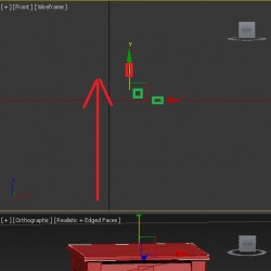
Use the front viewport to select your box if it’s not already selected, pressing the key “W” makes the move tool active so you can move the box in that front viewport up to the top of the table we have as reference. As you can see I zoomed in to make the final move on top of the bottom line of the reference table top.
| Hint You can also select lines, points and other geometry to move something, just hover over it until your mouse icon changes to 4 arrows. To change the axis constrain press “F8”, although sometimes you need to press it twice to get the correct direction, this way can be faster than finding the tool around the object its control point. |
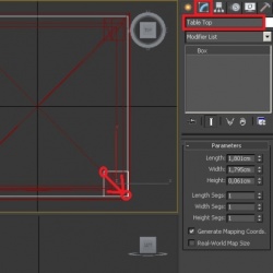
We will fine-tune the table top later, we first need to rename it and create the legs and other details first. Go to the edit model toolbar and enter the name “Table Top” as shown. After this, go back to making a box and create a box around a leg of the reference object like you did with the table top. This time to match the height as much as possible as well. Start working from the top viewport and use the perspective view as a reference view. Don’t worry about moving outside of the top of the screen for the height, the mouse button will appear on the bottom again as soon as you scroll out.
Repeat this action until you have all 4 legs and the use the move tool to fine-tune the left position over the reference model.
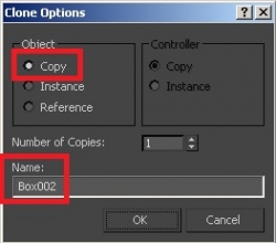
You can select your first leg and press the “Shift” key while dragging it across the screen to another leg. Once you release the mouse button a “Clone Option” menu will pop up, in this menu you need to select the “Copy” to object function and name the object “leg_2”.
Rename the one leg you haven’t renamed yet if you cloned them all, or rename them all if you made separate boxes. Then quickly scale them a little bit if needed and also move them a bit. For scaling use the “Tools -> Scale” menu, it works the same as the move tool. Or find the button on the top tool bar 2 icons over from the move tool to the right.
You can see now we already create a large portion of the table in a matter of seconds (if you don’t count the reading part, in my case writing ….).
I don’t want a center piece like this table with a drawer in it, I want to have 3 boards spread from bottom to top instead. To get this done we are going to start by making a box that is going to make up the same size later as the bottom board the reference object has.
You should be able to do this without help from here on out, so I’m going more into the creating 3 boards out of the one board. You just learned how to drag clone an object making the legs. This time we are going to use another tool to make all the copies at once at the place we want them to be.
Create, scale and move a box to form the bottom board and call it “Board”, then use the “Tools -> Array” tool and see the new configuration window pop up.
Again select the “Copy” option and now let’s duplicate this thing around an axis for a set amount of centimeters (in my case). Click the “3D Array Dimensions” and enter a count of 3 then set a value of “0.55” on the Z–Axis, now click "Preview" and watch what happens. If you like what you see click “Ok” if not fine-tune it to your taste and click “Ok”.
Now that we have the object we want we can start grouping and fine-tuning the scaling where needed. If you did it all correct you will get the following preview in your perspective view.
Colors may vary, as they are generated randomly when making objects.
[edit] Grouping simple objects
To create a solid object with matching sizes we need to take one element and convert it to something workable; in this case it’s going to be an element called “Editable Polygon”. With this element, or modifier, you can modify the object on the area you want to. You can merge other objects into your mesh to create one solid Group/Mesh to export or texture map.
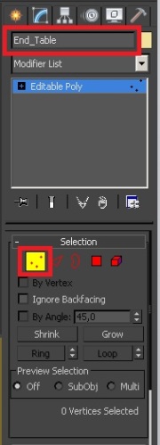
To do this select one object, let’s start with the table top for example. And right click in your active viewport to open a drop down menu, and then select “Convert to Editable Poly” from it and watch the edit toolbar change. Once you done this rename your object to “End_Table”, and enter the vertex select level.
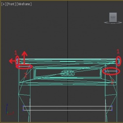
Select one of the top vertexes and start moving it around to match that side of the reference object, keep selecting and moving around vertexes until you table top is the same size and shape as the reference object. We will merge another object to this once we have the correct size for this object.
Now you only need 2 viewports to make this object the correct size, but feel free to use this stage to test around with the movements in 3ds Max a bit. As you can see in the screenshot I attached everything and then moved around the geometry.
I found the movement to be slightly off from most modeling tools I used, I had a few little issues with the perspective viewport but I learned to love the way you move around in 3ds Max its gives a nice and smooth handling.
Now let’s merge a leg to our table top and make that the correct size. You may have noticed that the reference objects has slightly sloped legs, we are not going to replicate that, and we want the top shape of the legs and nothing else.
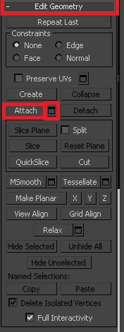
There are 2 ways of making this merge happen, both are done in the objects editable mesh settings under the tab “Edit Geometry” the options we are looking for is “Attach” and “Attach List” (the box behind it).
The first is selection based you can use a viewport to select the object you want to merge with. The second is based on a list, you get a list of object names and select our leg from that menu to merge with your table top.
It’s up to how you merge the leg(s) to your object, proceed with the leg you merge to match the top size of the reference legs.
Once you are done with the one leg repeat this around for all legs.
| Hint Is a certain object in your way? Select that object and use the right click menu on an active viewport to use the option “Hide Selection”. The object is now hidden until you unhide it true from this same menu. |
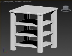
Now you can use the same learned craft to complete the initial object, attach all remaining objects and scale them to size after that, if you did the same as me the next picture will be more or less the same with the reference object hidden.
We are almost done as well with this object we need to prepare it for texture mapping and exporting. To finish the object we are first going to rename it to “Group_01” and then we want to add a few extra lines.
| Note: This next step is not really needed for simple objects with low detail like this one, 3D Studio max has an automated tessellation when using "Editable Mesh" objects. Just for the sake of showing the option I used it in the guide. The object will just work and show up perfectly without it. |
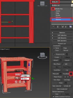
As you can see the reference object has some extra diagonal lines in the object. We are going to do this too, it’s a simple operation called “Tessellate” and can be found in the “Edit Geometry” tab.
For this option to show up as usable you need to be in “Face”, “Element” or “Polygon” selection mode and you need to select all Faces/Elements/Polygons ("Ctrl+A") for it.
The box behind it is the one we want, depending on your version of 3ds Max the menu may be different, but option should be the same. Set the same as my screenshot to get a similar end-result.
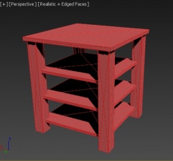
The end result should be similar to the following, if you have the same as me move on to the texture mapping part of this guide.
Be sure to make a saved scene of the progress so far. Next up is mapping the sides to make a wood grain fit in The Sims 3.
[edit] Creating a simple mapping
To create a simple mapping to form the basis of our texture, from here on out you can do without our reference object. You can either delete it or keep it on hide for the entire process. In 3ds Max you have a ton of modifiers to pick from to shape and mold the outcome of your model. I haven’t tested all of them yet in combination with The Sims, but I reckon that those making a solid object will work as long as you collapse them into the Mesh.
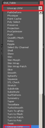
The one we are going to use now is called “Unwrap UWV”. This modifier can select object faces and vertices in order to create a texture mapping that suits you. The way this is being done is much like the UV mappers currently used for modding The Sims. The plus side here is that you can create simple base textures as well, this saves you using other programs to create “fake” shadows and highlights.
Let’s get to it and assign this modifier to our object, look at the screenshot for where to find it. Now in this mode, it has similar button to the editable mesh one, but as you can see only 3 selection mode, and a grey 4th if you're using 2013.
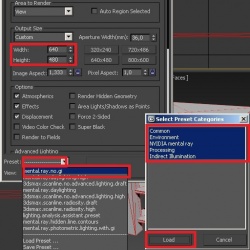
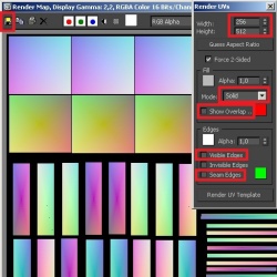
First we need to setup rendering and bitmap sizes, in order for this to come out properly we need every bitmap size to match the exported examples. The size we want is 256Wx512H Pixels, we need to set this both to render settings and to bitmap size in the “Edit UWVs”. For the “Render Setup” press “F10” (see screenshot where to find the settings you need to change), as you can see I set a render preset as well. If you do this now you won’t have to do this later. Now close the setup menu when done.
| Note: The render preset is only needed for 3ds Max 2013, 'cause else you can’t render the Occlusion mapping that we need. Don’t worry about loading things at this point we have our backup object already and are going to save this scene later under a new name. |
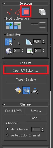
Go into the face selection and select all faces on the object using “Ctrl+A”, once this is done click the “Open UV Editor” box and be amazed by a new epic window (2011 and up got major improvements here, screenshots may be of from here on out, but option names are still the same). Now we need to do 2 things, as you can see we have 1 big red square now. We need to flatten this mapping a little so we can work with it, and then apply a texture to see how our grains are turning out.
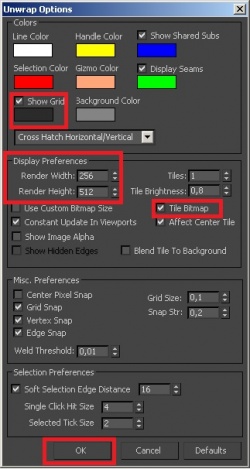
To do this go to “Option -> Preferences” on the “Edit UVWs” screen, or press “Ctrl+O”. Now you will see a settings window where we are going to change a few things before we move on. We need to set the bitmap size here we want to work with, so we can scale our mapping accordingly. I also turned on the grid with black lines and a grey background, and told the editor to tile my bitmaps.
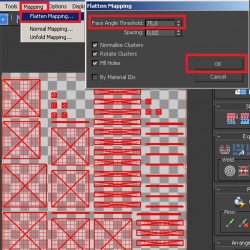
With all faces still selected go to “Mapping -> Flatten Mapping”, now a settings box will open here I only changed the “Face Angle Threshold” to a value of “75.0” this created for me a proper base mapping to work with. If you like to mess around with the setting to create your own mapping, feel free to do so. (Sorry about the 512x512 background I failed)
[edit] Editing that simple mapping
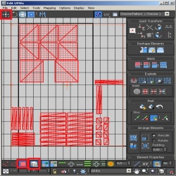
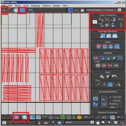
I moved the easy to map areas to the top by the all getting its own part on the texture mapping. The screenshot should show you all option on how to get the arrangement I made. Also, I moved the legs and sides of the tables to the bottom of the mapping, I'll arrange them later to match the wood grains. You can see the objects themselves are spaced from each other, but in between the groups are still large empty areas. This will sort now as well, and we will flip over some faces to match the wood grains we need. Also I kept the feet ends out of the bitmap for now, as you won’t be seeing much of these anyways.
| Hint: If you do need to rotate check the “Quick Transform” tab to the right. |
Ok now for the grain alignments, let’s say we have a wood texture with grains going from the top of the map to the bottom. For the table top and boards this isn’t a big issue, but for all sides and legs it is. If you look at our alignment the feet are currently having the grains from left to right projected, so we need to rotated them 90 degrees to get the pattern to go from top to bottom (read the hint above, don’t worry about moving them outside the texture map).
Now the sides are a little bit more complicated, the easy way is to select a part of the table top in your 3D viewport, and then looking in the editor how the face is turned. When you see the grain is going through that face you need to make the side align the same way. Bluntly said on the texture map you want the left and right side to be in the same orientation as the top/bottom half. This way the grain falls over the edge into the bottom section like as if it was a proper board. In the next picture you can see the rotated faces as a reference to how you might want it (yes I changed the line colors for this ><).
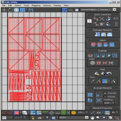
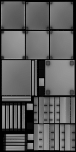
Now we have the objects aligned we need to scale them to match an equal size to what we have on the object. Currently everything is kind of torn slightly too much to the map size. You can see the table top is not square anymore, we want to slightly change this back same goes for any parts that are outside the dark lines square that makes up the texture map. Every single face needs to be inside the texture map when you are finished. The next picture is a view of how the texture map should look once you are done scaling things, the size doesn’t have to be spot on as mine, but do try to fill up most of the texture mapping areas to ensure you got as much as possible detail on each part you created. I used the table top sizes to scale my sides that I rotated, and I increased the leg size by the amount of spare space I had left after moving around the table tops. And in the spare spots I made the feet top and bottoms fit, also scaling them up a little bit more to fill up the holes.
[edit] Baking simple map textures
Now in order to create a good object we need textures to replace the one exported from your project. For this to work properly we first need to make simple extractions of our UVW mapping we just made; make sure to open the “Open UV Editor” option if it’s not still opened.
We can create simple paint backgrounds form this menu that provides a rather good basis for our final texture. To do this select the option “Tools -> Render UVW Template”, and take note of the new window that opens up.In the screenshot you can see the option I used to render all 3 maps from the drop down menu “Mode” under the “Fill” tab. Render and save all 3 option “Solid”, “Normal” and “Shaded” and name them something corresponding (I saved them all in .TIF 16-bit format to convert them into .dds later on in Photoshop and no, that is not our mapping that shows).
| Note: These basic texture mappings are the most basic there are, the normal mapping used here is far from the best normal mapping you can get on the object. But like many things these form a basis for the object in most scenarios. This table might not be the best example for this, but on more complex models you may get better results using the texture baking explained below. |
Now the harder part of making a material to assign to the object and making the final mappings we need, we need a shaded mapping with grey and white colors for the main map, and we need another Specular Map from 3ds Max with loads of white areas and only few shaded spots.
In earlier version of Studio Max this was easier to get done, for my 2013 part of the guide I will have to save my scene under another name again and do the material assignment and assembly part. I suggest you do the same for the sake of keeping a clean mesh. Since the object is done and mapped you can export it and work on the textures in other programs if needed.
Once you save your scene press the “M” key and if in 2012 and higher try not to get overwhelmed by option and cool looks. For this part we are going to build up our material starting to make a shaded base texture from the mappings we just saved.
| Note: The material editor has changed a lot since 2010, if you're using an earlier version and do not see any option you can relate to, make sure to read up on the tutorials from 3ds Max itself to get into this a little more I’m not using any advance option you cannot learn in less than 5 minutes reading. The names of the option are still the same but are not nearly the same to access as in 2013. |
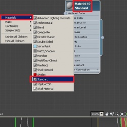
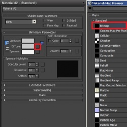
Right click in the material editor for max 2013 and select standard material from the drop down menu. Once you see this material in the editor, double click the material in the editor to make a new window show up, click the darkened square behind the name “Diffuse” and select “Bitmap” from the menu that pops up next. Then browse to the texture we saved before and select the solid map you saved.
Repeat these steps to input your Shaded map into the “Specular” slot and the Normal map into the “Specular Level” slot. You can also swap the Normal and Shaded map, or play around a bit with it, but I found this to give an average end result that was to my liking.
Now give it the following numbers for both “Specular Level” and “Glossiness”: 15/25.
Now make sure your object is selected and right click the material in the material editor and select “Assign Material to Selection” from the drop down menu.
This should already be the base color for your object; this color is later on replaced by the Mask mapping with a pattern from The Sims 3. You might think it’s a bit light, but these mappings are meant to be edited in Photoshop later on. Even though you can use these methods I’m showing to create really nice mappings I still like to use Photoshop for the final edits and shades.
Now we are going to bake this texture into a new texture that can be exported to Photoshop and later on import as a texture map. I’m going to leave the parts outside of 3D Studio Max up to you to do, as the tutorials written to import stuff in The Sims 3 cover this a lot smoother then I would ever be able to.
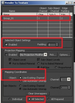
Now how to bake these 3 maps into the one mapping you see now in your 3d viewport. Go to “Render -> Render to Texture” or press the key “0” and again make sure your object is selected.
Check out the following screenshot to see if your settings are matching mine for the easy way of baking the texture.
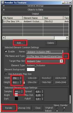
In the “Output” Tab click the “Add..” button and select “Ambient Occlusion (MR)” from the menu make sure to replicate all settings and also click the “…” behind “File Name and Type” to select a save location and format for you file (I again used .TIF).
Also make sure the texture is assigned to a “Target Map Slot” (Ambient Color in this case) And set the bitmaps to 256x512, repeat this process for all maps you can add using the “Add” Button try to match them to a corresponding slot like with the ambient map (although it’s not need to do so it prevents an error message from popping up that I’m not showcasing). Click on “Render” once you are done.
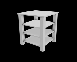
To check the results im going to change my material now with these maps, and add the “Oclussion” map to the Diffuse color the “Specular” to the specular color and the “Shadows” to the specular level map. You can see my end result when I rendered my picture.
[edit] Preview
Not bad for a start I would say, play around with these settings a little to see what suits you best, I’m going to merge these mappings we made to create a final mapping. The light one can be used as Specular mapping. I’m also using Photoshop to contrast another baked texture we made to use as a base mapping. This also because I’m not totally happy yet with my baked end results in 2013.
But for now texture and mapping is done, this object is ready for The Sims 3; we need to clean up the scene by converting our object to an "Editable Mesh". And save the scene again under a common name, exporting like this should not cause any issue using the same settings as import from the first Part of this guide.
[edit] Export
To export from here, select your object and use the “File -> Export -> Export Selected” option to export the selected object. The screenshot will once again show you the setting you need make it work with Milkshape.
From here on out you should be able to import this object into The Sims 3 tools you are using, and finalize/optimize the textures as well to import them to The Sims 3.
| Note: The process of baking textures is rather easy this way, sometimes the mappings don't get rendered properly. Some maps that are saved may even be black, the reason for this is cause we didn't bother using a light source for this guide, and 'cause I didn't go into the alternate setting too much. Learning on how to bake properly is a process of trial and error, the only way to get the textures you want is to try out settings and view the results. In later guides 'i will try to explain a bit more on this option, there are many ways to hide details into your Mesh textures this way. |
[edit] Afterword
I hope you enjoyed this simple guide and I hope this guide wasn’t too simple for your liking. Please feel free to experiment more with texture baking and mapping. 3ds Max offers an endless amount of options in this area, and I am only still learning the greatness of texture mapping and baking.
The next Guide in this series will cover advanced modeling and texture mapping, although again the texture mapping may seems rather newbies, it’s an easy way to show people how to work around some areas in 3D Studio Max that they may have done slightly different in other programs. Anyways, it’s been fun writing this, and I hope I taught some people a couple of things.
I hope to see you on my next tutorial on meshing in 3ds Max.
| Note: The end result is the final look for the object in TSRW, the mappings we made during this guide I mixed up in Photoshop to get a similar looking result as the exported textures. I saved the new once to corresponding correct .dds format textures and imported the lot as a low detail model. Total workflow time without typing this guide is around 20minutes and with that I even struggled still with the UV and Texture mappings. |
